Hardware for "Objects In Space"
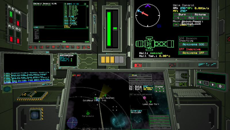
TL;DR: Objects in Space is an unique approach to combine flight simulators with an epic space game. You are the captain of a space ship, ready to explore a vast universe. Like any good simulator, there are a lot of buttons to press, so the creators of that game (two to be precise) built a interface to attach real hardware to the game. So you can build your own command center and control the game with it. How awesome is that?
 The game itself is currently in closed beta, but will soon become early access on STEAM (approx. end of June). I have the honor to test the game in the current beta state and play a little with the hardware interface. Because the game is not released yet, there is not much information on how to do that. There is an article and a protocol specification, but both are outdated and some critical information is misleading or is missing completely. So I will explain the minimal approach to create a little hardware device which will show the status for the main engine.
The Interface
To activate the serial interface, an additional config setting is neede. Open the objectsinspace.cfg file and add the following:
hardware=true
ignorecom12=true
The first option activates the serial console, the second skips COM1 and COM2 if your PC uses these ports as hardware ports.
After you start the game and open up a savegame, the game will try to open up a serial connection over a serial port. This serial port can be opened up by a microcontroller connected to a PC. Small development boards like an Arduino include a serial to USB chip to access the microcontroller from within the Arduino IDE (flash firmware, receive debug output, ...). This way, the game communicates with the hardware.

To start communicate with the game, the hardware device first need to fulfill a handshake. After that, the hardware specify what information is needed and what actions the hardware can offer. After that configuration, the hardware can switch to active mode and start reading events from the serial stream (the engine is burning, the ship is docked, ...) and send actions to it (start engine, undock ship, fire, ...). This information can be used to control the actual hardware (turn on LEDs, show numbers on displays, spin a fan, ...)
Handshake: After the serial connection is established, the hardware device need to initiate a handshake by sending the magic number
451\nto the game. The game answers with a452\nwhen everything is sane. Repeat this handshake until the game responds with452\n.Initialization: Next, we need to configure the needed information. This happens in the form
<TYPE>=<COMMAND>,<IDENTIFIER>\n. As an example:NIB=MAIN_ENGINE_BURNING,1\nwill receive the current status of the boolean action MAIN_ENGINE_BURNING periodically and on change, under the identifier 1. A more detailed description of the different types is shown in the OiS Serial Data Protocol page. A complete list of commands can be shown in a post from user zebra.Switch to active mode: To end the configuration and switch to active mode, you need to send a
ACT\nto the game. After this point, the game sends status updates when the status is changed ingame and periodically every couple of seconds. The receiving data is in the form<IDENTIFIER>=<VALUE>. In our example above, this would be1=1if the main engine is burning and1=0if the main engine is offline.
Programming the Arduino
To build the firmware, we just need to implement the steps above. First, we open the serial connection on 9600 baud. After that, we do the handshake. If this is successful, we configure one event and switch to active mode. In the main loop we read a string from serial and process the received message. If we get an 1=1, we switch on a LED, otherwise, we turn it off.
void setup() {
  pinMode(LED_BUILTIN, OUTPUT);
  Serial.begin(9600);

  // Handshake
  Serial.write("451\n");
  String serverResponse = Serial.readString();

  // Synchronisation
  if (serverResponse == "452\n") {
    Serial.print("NIB=MAIN_ENGINE_BURNING,1\n");
    Serial.print("ACT\n");
  }
}

void loop() {
  // Handle one response from the server/game
  String serverMsg = Serial.readString();
  if (serverMsg == "1=1\n") {
    digitalWrite(LED_BUILTIN, 1);
  } else if (serverMsg == "1=0\n") {
    digitalWrite(LED_BUILTIN, 0);
  }
}
Connect your Arduino to your PC and use the Arduino IDE to flash the code into the microcontroller. After that, the onboard LED will light up when the main engine is burning.
Sure, this is just a minimal example. To get this working reliably, there is some additional work to do like handling broken messages or lost connections. But you can get an idea how this is supposed to work. If you need more pins than the Arduino can offer, you can use a cheap shift register like the SNx4HC595 to attach even more stuff. For a cheap alternative to the Arduino, you can also use an ESP8266.